Basics / What you should know about high performance timingbelt gears
According to WIKIPEDIA, toothed belts (also called synchronous belts or timing belts in motor technology) are toothed drive belts that run positively in toothed pulleys. Toothed belts combine the properties of a chain and a flat belt.
On the inside of the belt there are teeth made of an elastomer which engage in a special gear wheel. The teeth can be made of rubber, chloroprene rubber, hydrogenated acrylonitrile butadiene rubber (HNBR) or plastic (polyurethane).
This design has the following advantages over V-belts or flat belts, which only work with frictional locking:
- The positive locking of the teeth means that high forces can be transmitted with lower pretensioning forces
- because the toothing prevents slippage, toothed belts can also be used for control purposes.
The force in the timing belt itself is transmitted by the embedded tensile cord, which is stiff compared to the elastomer and usually consists of glass or aramid fibres, less often of steel cables. The inside of the timing belt is coated with an abrasion-resistant fabric to protect the teeth from wear. Due to that fact, it is absolutely necessary not to damage the embedded tensile cord as example with a pincer.
In RC model making, the first timing belt gears were used in the 1980s as an alternative to toothed or planetary gears. The first "performance-oriented" timing belt gearboxes can probably be assigned to Kruse Modelltechnik with its "Synchro-Gear 800, 2500 and 2500 Duo".
One leitmotif was:" Electric motors do a lot. They can achieve even more if the speed is adapted to the requirements".
And here we are with the key qualification of every gearbox.
The charm of the timing belt transmission is its own:
- Quiet running
- very low wear
- very high efficiency
- easy maintainability
- Variability in reduction ratio
- good scalability of power transmission (belt width)
- wide speed range (running speed up to 80m/s)
- High position fidelity/ controllability
Can be / are disadvantageous:
- Size
- mass
- Size of moving masses in relation to gyroscopic effects
Today's timing belt drives have won through developments in the materials sector.
Profile/positioning accuracy, power transferability and belt speeds have improved/ increased up to 10 times. With low pitches (2 and 3mm), running speeds of up to 80m/s can be achieved as well as the transmission of power in the 2-digit KW range. Since industrial timing belts are also designed for operating times of 24/7/365, there is an additional "power reserve" for short-term applications such as RC model construction, which can be used with appropriate control/monitoring.
But where is the advantage for electric drives in RC-model building?
The starting point for all considerations should be the last link in the drive chain and the rule here is that the lower the speed and the higher the gradient/ pitch, the better the propellers.
If you feel like it, you can download the tool "PropCalc" from Helmut Schenk http://www.drivecalc.de/PropCalc/
You can obtain interesting insights there.
Some people have probably heard that the gradient should be at least half as large as the diameter (H/D > 0.5). In PropCalc you can see why.
Traditionally, however, our model airscrews have seen daylight in the era of the combustion engines and their speeds were/are sometimes very high (up to 16,000 rpm and higher). And that's why we have propellers with a dimension of e.g. 16" x 4" (first the diameter, second the gradient/ pitch, everything in inches). This results in an H/D of 0.25 and this is energetically quite suboptimal :-(.
In order to counter the lack of a small gradient, you have to increase the diameter significantly and . . . . . .whoosh, we land at the helicopter. In model flying with aeroplanes, this has a meaning when it comes to public-friendly "hovering". Looks spectacular, but is energetically suboptimal, since the diameter is actually much too small. And in normal flight you need an endless number of revolutions to move at all. Often a too low pitch of the propeller is also the reason for high power consumption, short flight time and dissatisfaction of the pilot. Also and especially with electric flying models.
Since the available energy is limited, the technology of the slowly rotating (LRK) external rotor motor has created an efficient means of propulsion for propellers with higher gradients and thus made some points in the overall efficiency well. But each electric motor has a characteristic curve and a specific speed. So each input voltage has a specific speed that matches or does not match the propeller. And the design, which worked great on the 6S-Trainer (1,6m span) with an 18" x 10" span, doesn't fit on the high wing with 1,8m span) for which I should better use 8S or 9S. The same engine would be able to drive a 16" x 8" propeller with this number of cells, but the speed just increases by 2,000 rpm and really comes out of the quark, doesn't do the whole thing.
Here a toothed belt gear helps us considerably. If it has variable reduction possibilities, it can bring the increased speed (from 6S to 9S) back down to a speed level where my high wing aircraft is now even pulled through the air with a 20" x 12" propeller. Since a bigger airplane needs more power, I did this, because with the increase of the number of drive cells this proportional increases. The efficiency of the engine has even increased by 2-3%, because it usually gets better with increasing voltage.
A timing belt gear thus turns a engine with a fixed speed constant (specific speed, rpm/V or Kv) into a engine with a variable speed constant.
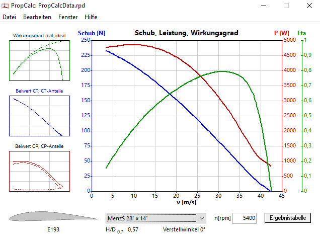
In order to improve the propeller efficiency, the speed should be reduced and the pitch increased. This can be a problem if no suitable propeller (pitch) is available or if ground clearance limits the propeller diameter. If you make a preselection with DriveCalculator, you should always pay attention to the value: Vpitch, because it tells us at which airspeed the propeller has its best efficiency.

As you can see from the green efficiency line, it has its highest efficiency at 31 m/s flying speed and I should stay there as much as possible during the flight.
Tip: Avoid speeds above 6,500 rpm and the lower I get (5,000 rpm) the better.
In connection with higher rotating helicopter engines, a toothed belt gear really comes out of the sun. We're talking here about engines with a specific speed in the 450-600 rpm (KV) range. If you compare the mass of such motors with an equally powerful direct drive external rotor, we often talk about half of it. Together with the lightweight single-gear gearboxes, the mass of the direct drive external rotor is sometimes even lower. The efficiency of helicopter engines is often more efficient, they can withstand higher loads and, thanks to gearboxes, they can be adapted more variably. The propeller forces are not applied to the motor shaft and bearings, and one and the same motor can be used for several models.
The following literature is recommended for those who would like to approach the timing belt gear from an engineering point of view:
- Dr.-Ing. Thomas Nagel; TU Dresden; Zahhriemengetriebe- Eigenschaften, Normung, Berechnung, Gestaltung.
- SDP/SI; Handbook of Timing Belts, Pulleys, Chains and Sprockets. www.sdp-si.com
- Gates design manual for industrial synchronous belts; EG/2009; ED 2005; www.gates.com
- eAssistant, The engeneering assistent; GWJ-Technology GmbH; www.gwj.de
We will be happy to advise you in all matters.
Your eAnSys-Team
